
So with the launch of JK3D (more on that in a future post) I was testing my laser engraver/cutter on etching my logo into 3D printed parts. In most cases that will be easier/higher quality/and more discrete than 3D printing the logo on stuff.
The Problem:
The trouble I ran into was knowing exactly where the laser was aligned to the design. I have a grid of dots on the perimeter so I know per 10mm where the alignment grid generally is, but knowing where on an actual complex part where the laser will fall is more difficult.
Mounting small laser diodes to the head can be a solution but the lasers wont focus in the right area as the table moves up and down for different objects. You also never exactly know if you bumped them or they are not aligned with the main beam anymore. The fix is to send a laser down the main beam path, but to do this you normally need expensive beam splitters and alignment is a pain. I wanted to do this a different way.
The Goals:
I wanted a solution that meets the following requirements –
- Uses the main optics and beam path
- Uses a small laser diode that can run on 3.3 or 5v.
- Doesn’t interfere with normal laser operations and is generally automated
- Must be repeatable
- Must be inexpensive and optimally use parts I have (I have laser diodes)
The Solution:
I looked at how the printer functions and one of the key items on a K40 is an arm/disarm switch that needs to be depressed in order for the main laser to fire. It is a simple switch that connects directly to the power supply to control current flow in the PSU itself, almost no real current goes over the switch. So I know I can use that to enable a sighting LED. But… how do I get it in the beam path and not interfere with the main 40W laser?
I realized I have a few micro servos from some other Arduino starter kits… what if I swung a laser diode into the beam path when the main laser is disarmed, and swing it out of the way when the the main laser arms? Hmm.. I took some measurements and went to work in Arduino IDE and FreeCAD.
The BOM based on what I had in hand. I didnt need to buy anything for this project.
- 1x NodeMCU ESP8266 board
- 1x 5v 6mm Red Laser Diode
- 2x 3v Relays – Using one to switch the main laser safety, and the other to switch 5v for the red laser. – I ended up not using the 2nd one, and just driving the laser off the 3.3v logic voltage for now. Relay I used is what I had on hand : https://www.seeedstudio.com/Grove-Relay.html
- 1x micro servo (simple Arduino kit 9g micro servo) – including stock fixings.
- 4x 10mm counter sunk rare earth magnets
- 1x Project breadboard (50x70mm with 2mm corner holes is what I had here)
- 5x various JST XHP 2.54mm connectors, both solder-on male connectors and crimp on 2 and 3 position female.
- 6x 2mm screws to mount the project board and relay to the plate I 3D printed
- Various wire.

NodeMCU Proof of Concept testing 
FreeCAD designed arm and mount 
Arm out of the beam path 
4x 10mm counter sunk magnets 
One of the magents 
Test fitting 
First print and it worked perfectly.


Arduino and the NodeMCU/ESP8266 board
First step in testing was to ensure I remembered how to program an extra NodeMCU board I had sitting in a box. It would be the perfect programmable board to handle driving the servo and the other tasks.
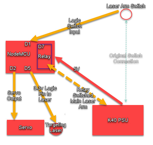
The basic flow is to have the NodeMCU and a Relay replace the main laser arm switch and use the switch itself to trigger a logic routine that would turn on the targeting LED, and swing the targeting LED. This was easily done and included Arduino OTA programming on the board itself.
Included below is the final code I used. I am only swinging the servo 45* out of the way. Note, the code is called out as using a relay for the targeting laser, if I used a relay no code changes are needed just need to swap the relay into the line. Also note, that the last time I worked in Arduino IDE was 1.5 years ago…
#include <ESP8266WiFi.h>
#include <ESP8266mDNS.h>
#include <WiFiUdp.h>
#include <ArduinoOTA.h>
#include <Servo.h>
Servo laserservo;  //Servoname

#ifndef STASSID
#define STASSID "<redacted>"
#define STAPSK  "<redacted>"
#endif

const char* ssid = STASSID;
const char* password = STAPSK;

//variables for the relay and servo
const int buttonPin = 5;     // the number of the pushbutton pin
const int ledPin2 = 2;      // the number of the LED pin - Onboard LED
const int ledPin = 16;      // the number of the LED pin - Onboard LED
const int redlaserrelayPin = 14; //D5 R1
const int co2laserrelay2Pin = 13; //D7 R2
#define servo1Pin D2 // Define the NodeMCU pin to attach the Servo

// variables will change:
int pos = 10;    // Start Servo at position 10


void setup() {
  Serial.begin(115200);
  Serial.println("Booting");
  WiFi.mode(WIFI_STA);
  WiFi.begin(ssid, password);
//Commented out the below because I dont need the WiFi to be up when I power the board on for it to work, if you do uncomment the below and the ESP will wait till the WiFi connects to run.
 //while (WiFi.waitForConnectResult() != WL_CONNECTED) {
 //   Serial.println("Connection Failed! Rebooting...");
 //   delay(5000);
 //   ESP.restart();
 //  }
  ArduinoOTA.setHostname("TargetLaserESP");

  ArduinoOTA.onStart([]() {
    String type;
    if (ArduinoOTA.getCommand() == U_FLASH) {
      type = "sketch";
    } else { // U_FS
      type = "filesystem";
    }

    // NOTE: if updating FS this would be the place to unmount FS using FS.end()
    Serial.println("Start updating " + type);
  });
  ArduinoOTA.onEnd([]() {
    Serial.println("\nEnd");
  });
  ArduinoOTA.onProgress([](unsigned int progress, unsigned int total) {
    Serial.printf("Progress: %u%%\r", (progress / (total / 100)));
  });
  ArduinoOTA.onError([](ota_error_t error) {
    Serial.printf("Error[%u]: ", error);
    if (error == OTA_AUTH_ERROR) {
      Serial.println("Auth Failed");
    } else if (error == OTA_BEGIN_ERROR) {
      Serial.println("Begin Failed");
    } else if (error == OTA_CONNECT_ERROR) {
      Serial.println("Connect Failed");
    } else if (error == OTA_RECEIVE_ERROR) {
      Serial.println("Receive Failed");
    } else if (error == OTA_END_ERROR) {
      Serial.println("End Failed");
    }
  });
  ArduinoOTA.begin();
  Serial.println("Ready");
  Serial.print("IP address: ");
  Serial.println(WiFi.localIP());
//NON OTA CODE
    // initialize the LED pin as an output:
   pinMode(redlaserrelayPin, OUTPUT);
   pinMode(co2laserrelay2Pin, OUTPUT);
   pinMode(ledPin, OUTPUT);
   pinMode(ledPin2, OUTPUT);
    // initialize the pushbutton pin as an input:
    pinMode(buttonPin, INPUT);
    laserservo.attach(servo1Pin);  // attaches the servo pin declared above
}

void loop() {
  ArduinoOTA.handle();


  //NonOTA Items
      // read the state of the pushbutton value:
    int buttonState = digitalRead(buttonPin);

    // check if the pushbutton is pressed.
    // if it is, the buttonState is HIGH:
    if (buttonState == HIGH) {
        // Laser Power Button is Off, Turn the CO2 Laser Off, adn Move the Servo into the path
        laserservo.write(10); //Lower Servo to put the Targeting laser into position
        digitalWrite(redlaserrelayPin, HIGH); //Enable Red Laser
        digitalWrite(co2laserrelay2Pin, LOW); //Disarm CO2 Laser
        digitalWrite(ledPin2, HIGH); // Set LED On
        digitalWrite(ledPin, LOW); // Set LED off
    }
    else {
        // Laser Power Button is On, Move the red laser out of the path and arm the CO2
        laserservo.write(45); //Move Red laser out of main beam path
        digitalWrite(redlaserrelayPin, LOW); //Disable Red Laser
        digitalWrite(co2laserrelay2Pin, HIGH);  //Arm CO2 Laser
        digitalWrite(ledPin2, LOW); // Set LED OFF
        digitalWrite(ledPin, HIGH); // Set LED On
    }


}
Once the proof of concept was done, I went to implementing the proper connections and such on the project breadboard. I designed and printed a quick tray to hold it that turned out better than I thought. The board has a second 5V plug on it so if I end up running the LED off 5v I have easy access to it.

Final Mounting 
Under the PCB wiring 
Custom tray for the NodeMCU and Relay

Install/Testing:
The stock laser arming switch on this K40 is a normal JST HXP connector so I was able to simply unplug it from the PSU and plug the switch into the board with no modifications to the switch or PSU.

New board in the electronics bay of the cutter 
M2 Nano Pinout to find 5V easily 
5V tap from the back of the M2 Nano laser controller board
Video of it in operation:
Beam Alignment
So as you can probably expect the folded metal frame is NOT true and flat on these cheap laser engravers, the “10 for $6” laser diode optics are questionable, and the inherent precision of 3D printed parts means the alignment of the beam may be all over the place.
To solve this, use the 4 screws holding the magnets onto the servo mount. Back them out to adjust the angle and tilt in all 3 dimensions as needed. It took me a bit but eventually it worked out! It doesn’t need to be dead on accurate and perfect, but I wanted it to be shooting the red laser in the same hole I just burned with the CO2 Laser and it is close enough. Since its on with magnets, its very easy to move and reposition as necessary.
Conclusion
First “production” use pictured below. I mark the place I want the engraving to go on some tape, then place the object on the cutting tray, and move the gantry in both X and Y along the lines to ensure that the part is aligned with the X and Y axis. Once that’s done, just tap the “Arm” button and go to work!


This was a rapid fire project, From Sunday night realizing I had an idea, to Tue mid day having the project 100% done. Longest task was getting the parts printed, designing them was actually very very fast. You want to replicate this project? Check the below links!
Where can you get the 3D printed parts? Well… Since I used a lot of open source help to design the code for this, I am posting the parts on Thingiverse!
You can also drop me a line on JK3D.us to print a set for you if you would like.