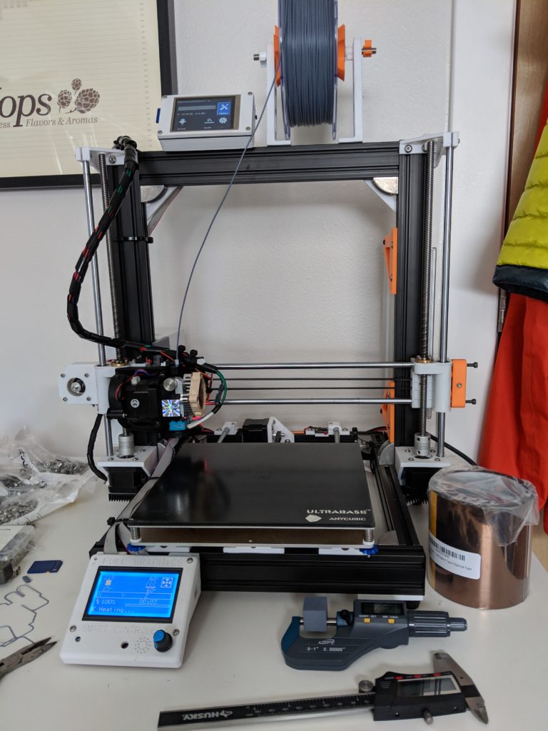
I’ve started printing test parts for the new printer. These are all being done in cheap eSUN PLA+ as to not use up my expensive CarbonX on testing.
The first test prints were done with the printer in our garage (semi heated, but… its winter) and the results were crap. I am starting by printing the most complicated part for this printer, the Y-Axis carriage.
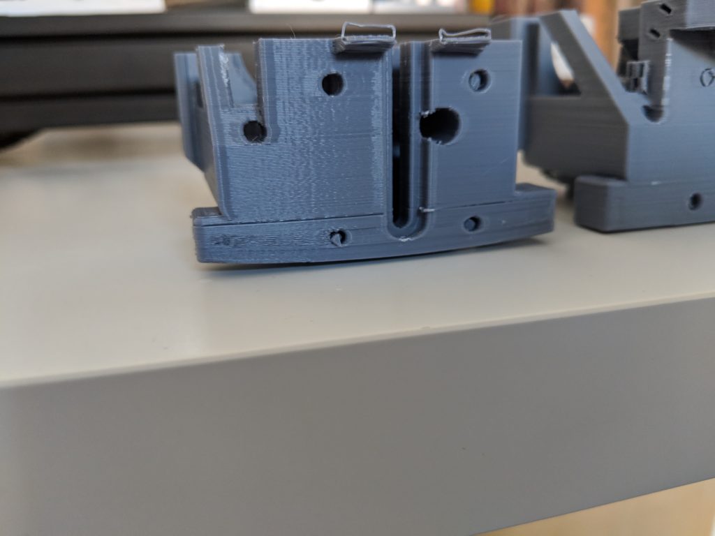
I stopped the print twice after 60% done because I saw enough to know what was happening. There were a number of issues discovered both with the part design, printer settings, and slicer settings. Some of these were rookie moves, others were subtle settings in the printer firmware that I forgot to tweak before printing.
Problem 1: My print settings and printer config were shit.
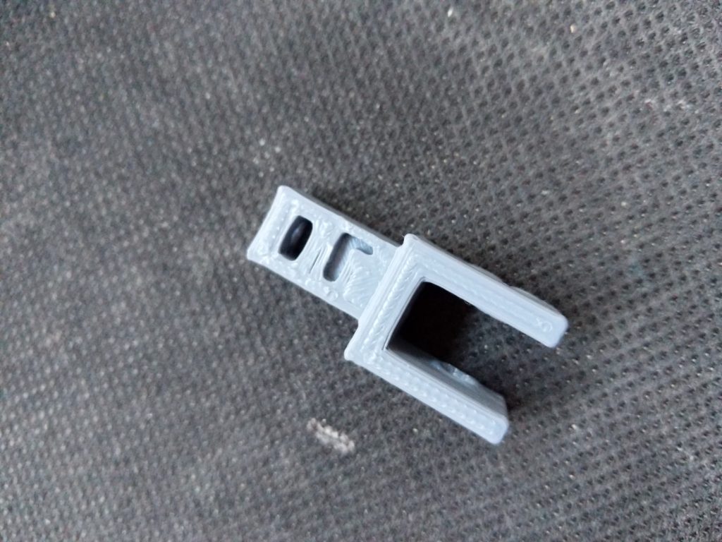
This profile I was using for the print is the same i’ve used before, but for some reason everything was shit. Corners bulging, what seems like over extrusion, and dimensions off by close to 1mm in some cases.
I found the extrusion setting was set high in the slicer, so I knocked that down. But the bulging corners and dimensional things were all the printers fault. I had calibrated the steps per mm on each axis, but it wasn’t adding up. So I ran another series of calibration tests with a known good model.
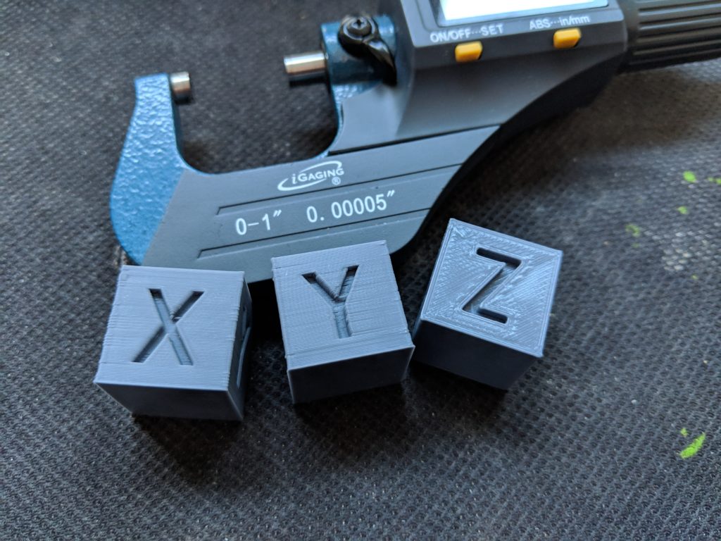
I attempted to resolve all the problems in 3 cubes. 1. Fixed the steps per mm on the X axis and verified the Y and Z are accurate. 2. I also changed the slicer to print outside->in to maintain outer perimeter tolerances for size better. I adjusted the speed as well. 3. Adjusted the printers firmware Acceleration and Jerk settings to reduce the bulging in the corners.
Once that was done, the printer was in good enough shape to start over again trying to print. And this time in my office where it is more temperature controlled.
Problem 2: My 3D design was functional, but shit
One thing I discovered (and I’ve had this trait for a long time…) I would design something to be purely functional not thinking about the printing process for it. For FDM, and SLA printing that is a big deal. These objects are printed in layers from the build platform up. You need to print them in a way that is compatible with the material you are printing, and so the bonding layers have strength in the right direction. Now this is not always possible, and for the Y-Carriage I am printing, it will have forces applied to it in 3 axis (Y, X, and a rotational load along the X Axis.). So no one printing direction will work better or worse in this case. BUT… printing from a flat surface is a challenge with an object with no big flat surface to rest on the build table.
Another aspect that causes problems there is supports. Supports are the structures built around and under your objects to ensure they can print in overhangs. Typically anything over 45Deg hanging over the build surface needs supports (more or less depending on the material).
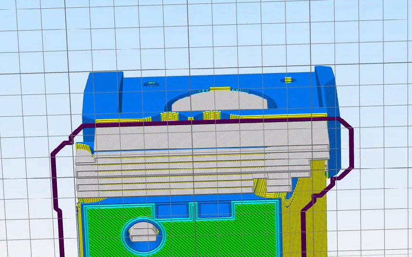
More (traditional) supports you need, the more potential for problems in your print I’ve found. The original Y-Carriage design had some big problems with this, a ton of 90deg raised overhangs. This not only slowed down the print time extensively but also caused a small footprint to be actually anchored on the platform during the print.
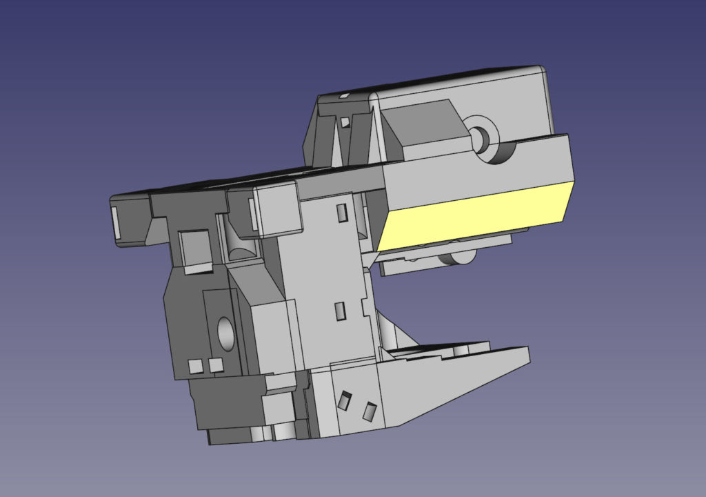
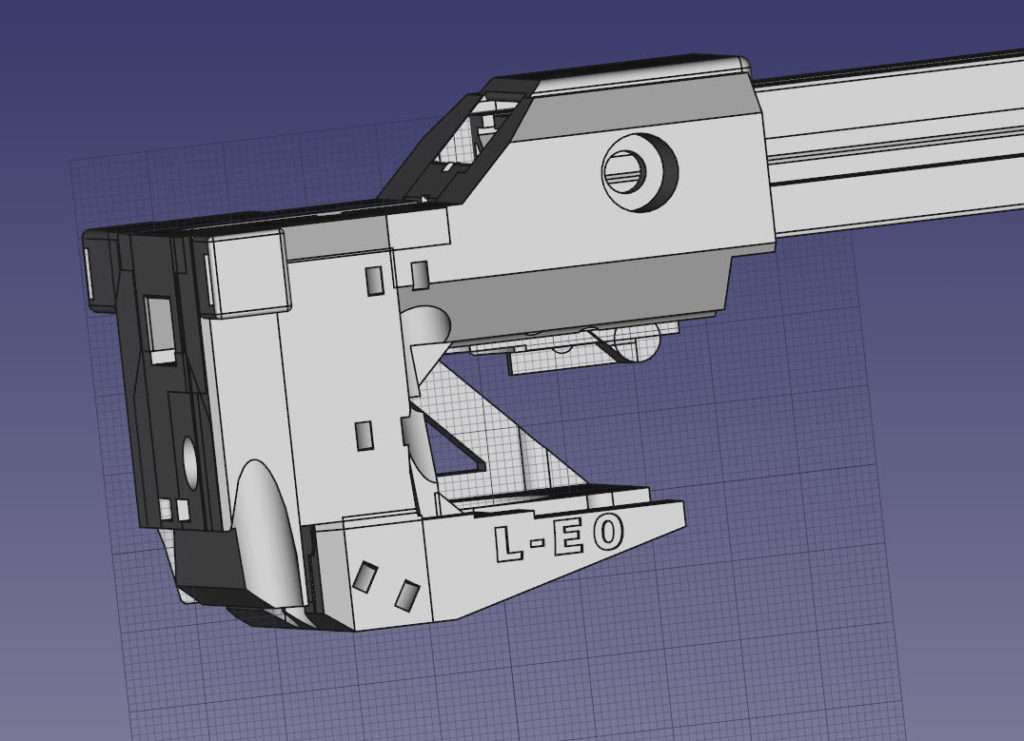
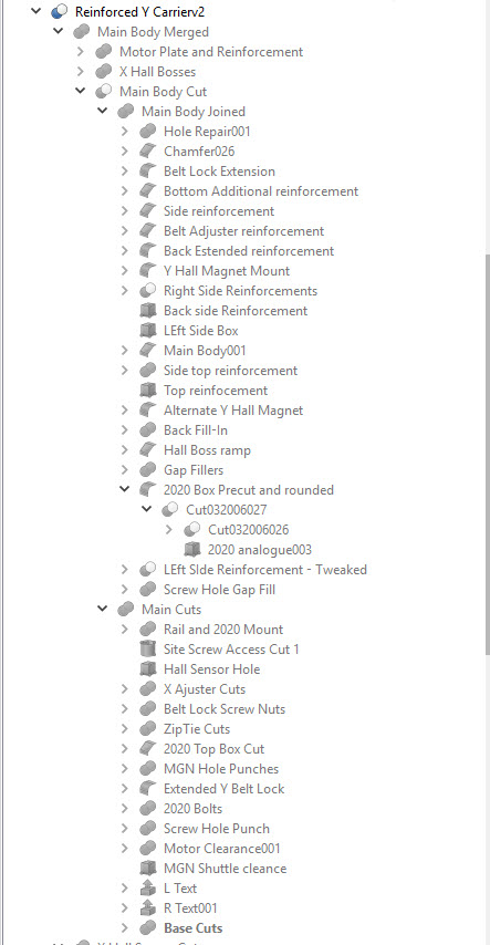
I knew there would be some hurdles when I started printing the parts, the problems I had with this part caused me to go back to the drawing board and take a serious look at overall function and design. Because FreeCAD is parametric, I can easily jump back in the build tree, and make changes. I can insert and remove components, change specs, and tweak away and let the changes cascade back up the tree.
I ended up making a new carriage that is not only visually much more streamlined and clean, it’s also simpler to print, stronger, it brought in a bunch of design ideas I was working on as well. I even had time to label the sides. This one carrier will be printed twice and one on each side of the X Axis. So one side lists the R-E1 and L-E0 on the other. Denoting which side is home to Extruder 0, and which is home to Extruder 1.
Part by part I will be going through this process to test print, check it, tweak the design, reprint, repeat until the part is ready to go for “production” prints.
Nylon is more fussy than PLA by a pretty big margin so that will be printed with even more care to ensure successful prints. The Kapton tape in the top pic next to the printer will be the build surface for the Nylon to ensure it grips the plate best.
In other updates – the materials arrived for the printer, but not without some mistakes in ordering.
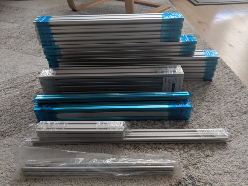
One of the mistakes I found immediately is the 2 most expensive bits of metal in that stack (the blue wrapped 3060 bars) were ordered incorrectly. These blue bars (and the 2020 one on the top) are all milled to a precise flatness on 2 sides for mounting linear rails to them. Generally Aluminum extrusions would have some variance in terms of profile that could cause issues or uneven rail mounting.
Well with the 3060… they milled the edges… I needed the 60mm flat parts done. Turns out that is a 6030 rail. So, $60 down the tubes and new ones ordered. As well as a number of other fitment parts (better T nuts than what I had previously ordered, more screws, washers, etc…) still coming in.
So the lesson learned. Pay very very close attention to part numbers and specs when ordering things from Misumi.
That and the Duet2 Ethernet mainboard I have been testing has a bad ethernet port on it, so I am getting that RMAed. Thankfully there is no timeline on this project.
Update:
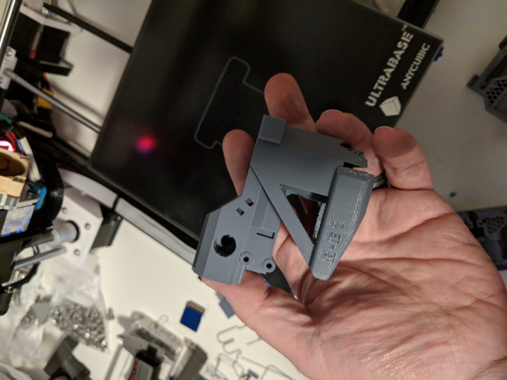
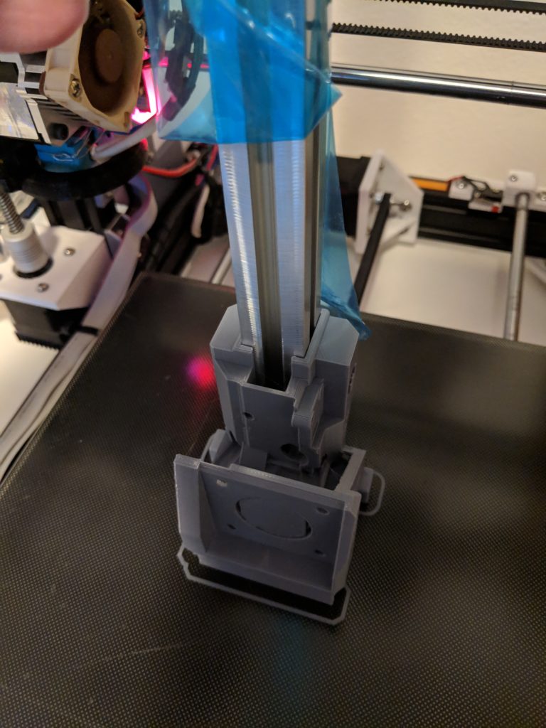
I finished the updated print and it looks perfect. Only 2 small tweaks, but besides those this part is done! Now when I print in CF Nylon the tolerances could get a little tight. I should be able to compensate with some test objects.

Leave a Reply