One of the biggest hurdles of this 3D printer project is designing the custom parts for it. The metal work is pretty straight forward, if complex to get all the dimensions together.
Source Materials:
While everything in this printer is being custom drafted for it, there are a few sources I used for inspiration, dimensions, and geometries. An example is the carriages that carry the X Gantry along the Y axis. The parts I have modified all came from Thingiverse, or MFG CAD files you can download (Pulleys, Rails, Nuts, Screws, Aluminum Extrusions, etc….). I’ve leveraged McMaster-Carr a ton for part CAD designs to verify fitment.
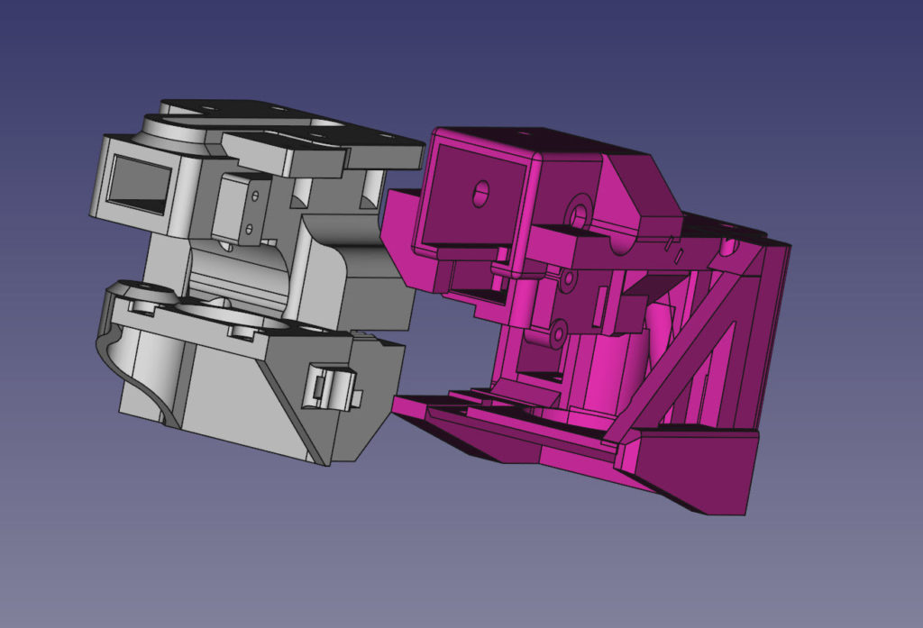
Most of the parts were modified to accommodate new geometries, reinforcement, different motors, different metals, different linear motion systems, different build volumes, etc… The vast majority of the work on this printer has been doing these kind of changes. A number of parts are from scratch though. In the case of the Y Carriage – only things really kept was the MGN15 rail mount and the geometries of the motor position. My design uses different sized motors, has a 2020 rail above the linear rail, has an adjustable X Axis belt tensioner, hall effect endstop, and is built much heavier to accommodate the heavier motor, and higher speeds I am aiming for.
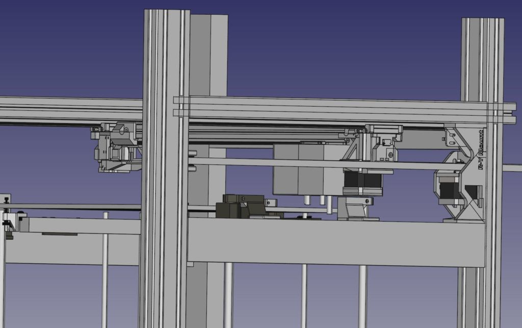
There are 4 different levels I am designing this printer:
- Component level- Individual parts
- Sub Group level – Parts that need to work together
- Axis level – All the parts for a specific axis (X/Y/Z/Extruders)
- Full integrated system
The process is recursive – and moves from both directions. I started at the full system level to define the “box” I need to work in, then form there defined the axis requirements, then designed the components to that. I would then flow those changes and parts back up through the tiers to verify their fit, work together with the other parts, and overall meet the requirements. If I ran into a part that didn’t, I would go back down a level, tweak it , and move it back up.
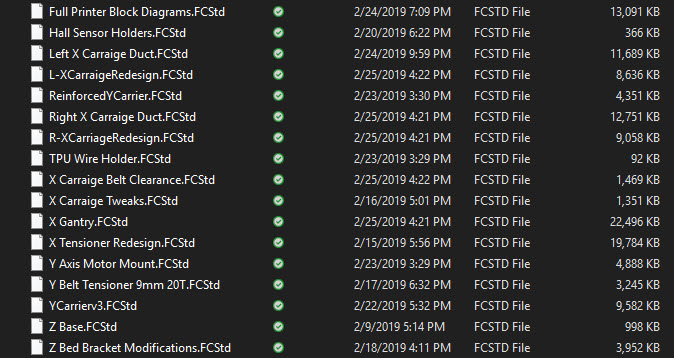
I have individual files for working on the specific components, then other work environments/files that contain larger systems, and then all the all up printer design. This keeps things a bit more organized, but still these files and workspaces get cluttered as a workbench would in a project with lots of tools and parts being used. So at some point I “fork” the design into a new file, and start working from there dropping lots of the trash that accumulates in the component lists.
Work the system in fully in CAD before printing anything:
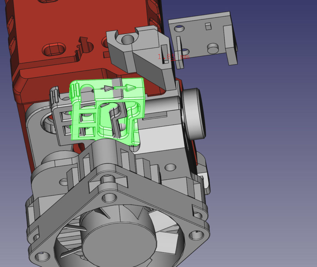
I leverage FreeCAD heavily in this process. Not just to design, but verify function, clearances, and overall concepts. Since many parts on this machine are very small clearances are being measured by sub .5mm (designed to .1mm tolerances, but giving some room for the randomness of 3D printing). It is difficult to understand all the variables and movements in components, so this makes it much easier.
Also being able to check clearances on items that will be hard to work on and get to later on. I’ve caught a number of design issues I’ve had to fix for small changes that cascaded into multiple changes down to the other components nearby.
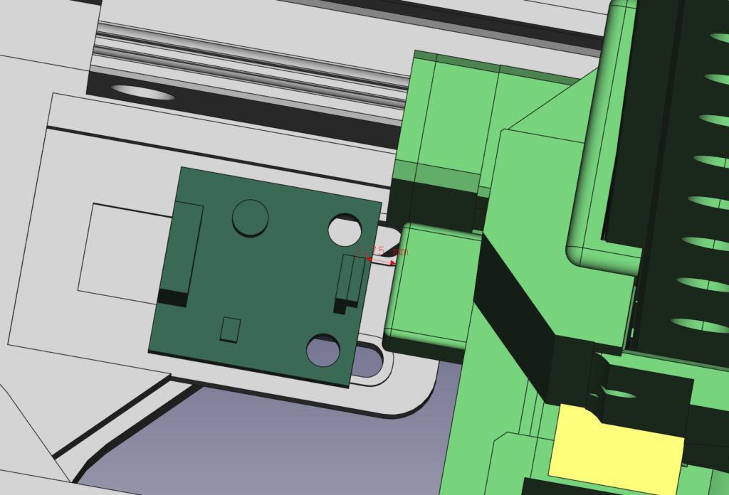
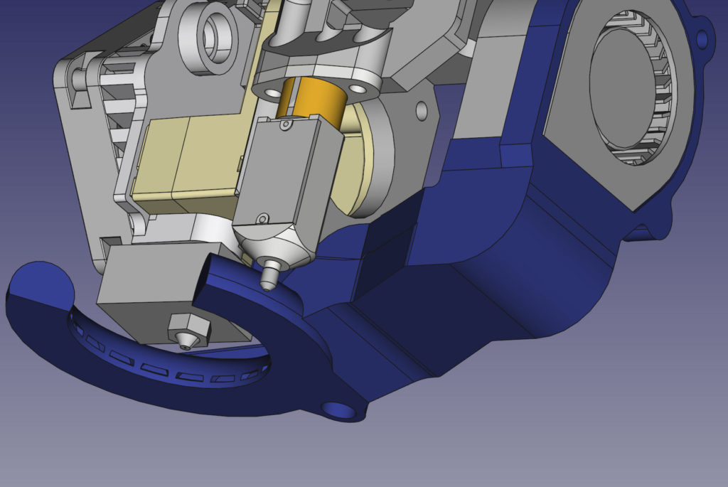
One ofthe most challenging things to work around in this was to design a new fan duct that worked well, but also left clearance for the Z height sensor, and wouldn’t interfere with the other extruder. It took ~ 10 hours to design and finish both for the L and R Extruder.

The X Axis belt configuration was challenging as well… the belts run through the two extruder carriages, and the original geometries were for 16T pulleys and idlers on both sides. In this printer I am using 16T Pulleys and 20T Idlers on the ends (Due to availability, and also it reduces some wear and “noise” on the belt. ). This offsets the center belt runs by about 1* parallel to each other. So not only does this require the Y carriers to change their geometries, but both X Axis carriers needed to be tweaked. The only way I could do it easily was trial and error, modifying the holes in them and “sliding” the carriers along the belts to see where they would have interference.
The goal is to have minimal redesign once the first fit checks happen. I know this wont eliminate everything, I am expecting some tolerance and interference issues on first build. But it should be easily dealt with at that point.
Just a hack:
I am not an expert at 3D design… I am a hack. These tools come to me pretty intuitively, even if I am probably using them wrong. I’ve designed a number of other things around our house over the years and printed them. But this printer design is a magnitude more complex and has resulted in me being forced how to approach this stuff a bit more methodically.
FreeCAD is … free. Go download it, fire it up and play with it. For a free open source CAD program its pretty fast and easy to use. But can be as complicated as you want. I also use AutoCAD Fusion360, but I am not very good at the tool so I am not spending much time in it right now other than for some of the unique tools it has that FreeCAD may lack.

Leave a Reply