
While on vacation over the weekend I took advantage of an offer to use a drill press at my sister in laws work. (Which just so happens to be a military base, so its like I was using my own drill press since I kinda own part of it 🙂 ) I was able to go through the process of drilling the 16 holes in the plate I needed in order to mount it on the printer.
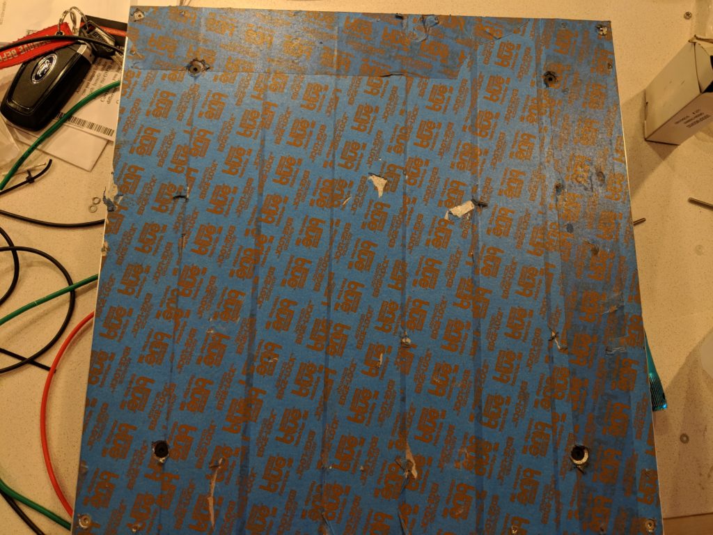
This is a 1/4″ 6061 tooling plate, and I am mounting a 750W 120v Silicone heating pad under it. The Pad itself has 4 mounting holes to secure it to the back of the heated bed, so the total hole count was 16 I had to drill in.
- 4x 3mm corner mounting points (counter sunk and then filled with 3x50mm flat head screws),
- 4x 4mm Heat Pad mounting points (counter sunk and filled wiht 4x18mm flat head screws with big washers on the back)
- 8x 3mm ( Drilled at 2.5mm to be tapped) these are for the corner locks I am designing and going to have printed in PEI/Ultem to hold the print surface in place.
- 2x 3mm (Drilled 2.5mm and tapped) using one to mount the 135C thermal fuse and grounding point to.
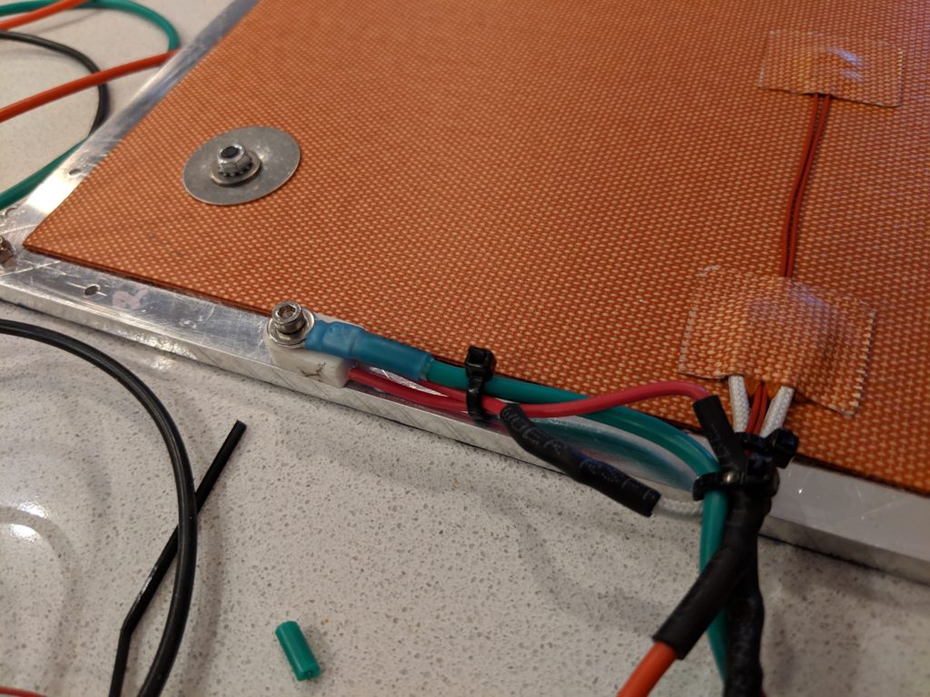
For 120V heated beds, its important to ground the heated bed to avoid any potential issues, it also helps regulate the EMF given off from the bed a slight bit which could affect leveling accuracy at times. I used a single hole to mount a 135C ceramic thermal fuse (to cut the power over that to the bed), and the grounding point.
All the wires were upgraded to highly flexible, large gauge silicone wires for the run through the drag chain. The thermistor was terminated in a Molex Micro fit 3.0 plug and extended to the Duet.

Wire bundles coming up from the Z table drag chain, the Y Axis motors, and the U Axis end stops/motors 
The AC power is run seperate from the Thermistor wires 
The Wire bundle drops down the drag chain pretty cleanly. 
Initial AC Power run for the SSR and up to the table
Mounting the heated bed itself


I used some hard fiber electrical insulating and thermal insulating standoffs, and my own designed NylonX blocks to mount to on the Z table. There is a 50mm long 3mm screw run down through there with 2 locknuts to keep things stable. Overall the table was nice and flat/consistent corner to corner from some basic measurements when installed.
Powering the Heated Bed:
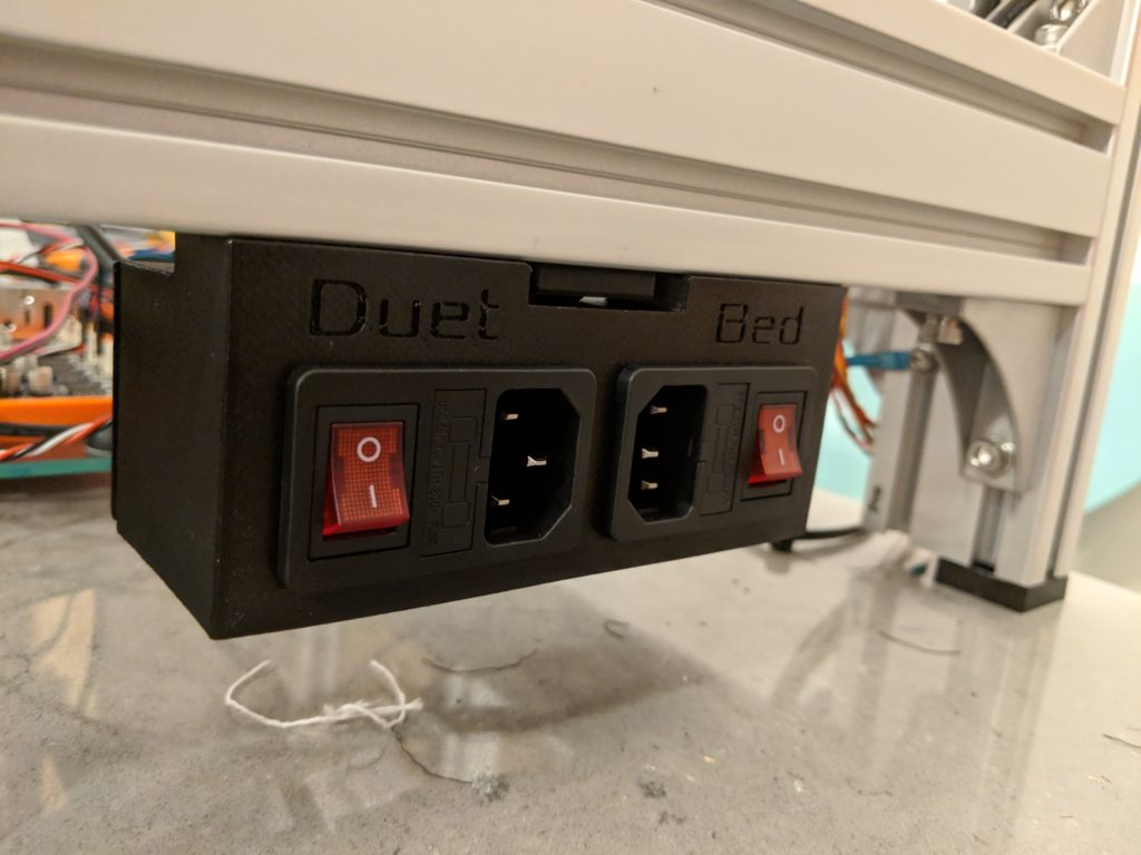
I printed a box to hold 2 power inputs, one just for the bed with its own 8A fuse, and the Duet with a 5A fuse. This will let me spread the load between two circuits, and also have a dedicated fuse to blow if either system have a catastrophic issue.
Initial Bed Heat testing:
I fired it up, and turned it on to 70C in the Duet, and it hit it in under 45 seconds. I put it to 115C and it made it there in ~ another 60 seconds. This thing heats up massively fast, and takes a long time to cool down due to the high thermal mass in the bed. This should do just fine 🙂
Next Steps:
Next step is to get the stepper wires extended for the X and U axis, get the wires run to the X and U Carriages, and then test out the U Carraige Titan Aero on its first heat up/print. But there is a long way to go still… But orders for wire/parts/etc… should be pretty much at an end. Now it’s just finishing the actual implementation.