
Tonight my Anet AM8 printer was running non stop, I was designing non stop, and building non stop. I was designing parts and pulling them straight from the printer as I went, rinse and repeat.
The X Carriages (X and U technically) and wiring them has been a troubling prospect. Since these are direct drive extruders I need to run 12 conductors to the extruders in a way that hopefully won’t impact the movement of the X or Y axis, and still be stiff enough so it doesnt droop onto the work.
I’ve posted before (see this post) about some of the designs I did for the X Carriages to allow me to plug in the items on each one as needed. After 3 revisions on the initial designs I finally got them completed. Below are pics of the implementation:

The Right side X Carriage (U Axis) wired up. 
Left side X Carriage prepped, and checking the clearances 
Both X Carriages 
Molex Microfit 3 connectors 
My chicken scratch to keep the wiring consistent. Each X Carriage has 2 sets of 6 conductor ribbons to keep track of. 
Clearances are tight! 
2 6 conductor ribbons into a TPU sleeve with Capricorn Bowden tube running over it. 
First install of all the connectors 
Initial wiring of the Microfit connectors
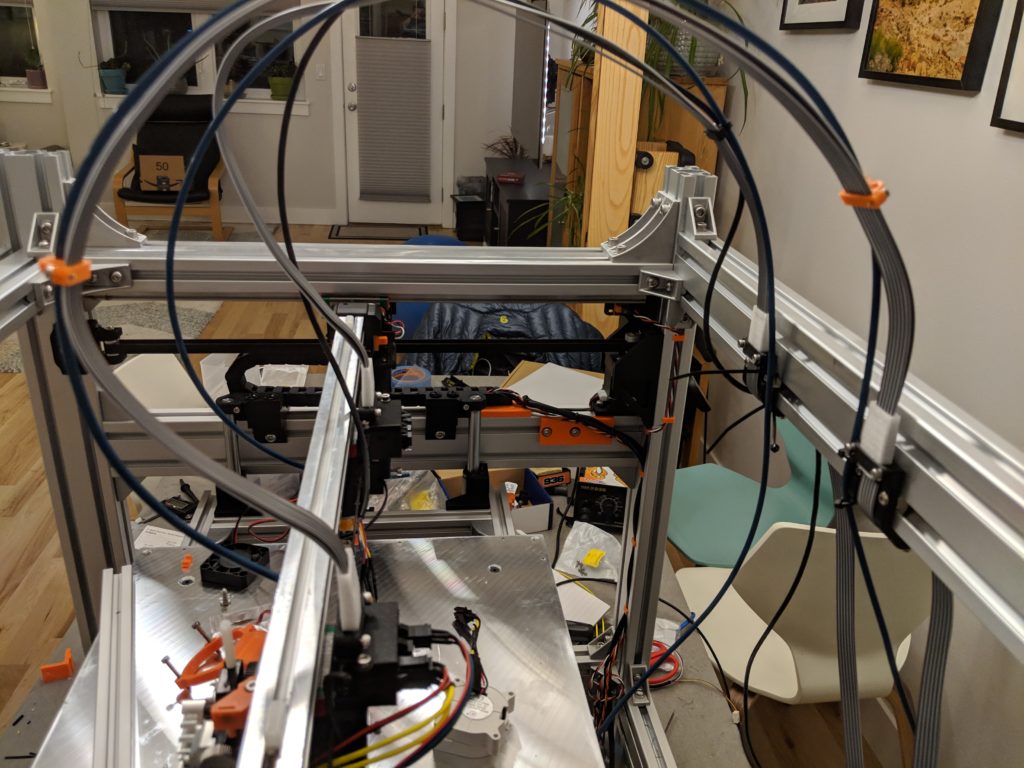
Like in the first photo the Bowden tubes I am using to feed the filament to the extruders (Pulling the filament vs pushing) acts as a bit of a support structure. The left side X Carriage also has a wire run over it that handles the BL Touch sensor.
The other side of the mounting:
getting the wire attached on the X Carriages was one thing. I needed to get the wire secured on the frame on the other side. I needed it to be as tight to the frame as possible as to not interfere with the X Carriage movements when they are in the parked position.

I also have a requirement for this build that nothing can extend outside of the frame (Making enclosing it easier) So I designed an anchor to grab the wire, and then in a controlled radius route it back and down.

2 Part design, the main bracket that rolls the wires under the 3060 chassis frame 
And a bottom clamp designed to roll the wire back down and out of the way.
The bracket worked on the first try. Very few things I’ve designed in this project have worked in the first iteration. This one worked so well I printed another and have the mountings done! It also has a channel to guide the Bowden slightly out of the way, and the bottom clamp has a gap to let me run the BL Touch wire through it.

Both cable mounts in use. 
Simple and elegant solution for this. When the Polycarbonate panels are put on the wire will run down the inside of that.
The Bowden tubes will run straight down to 2 dry boxes that will be installed in the printer in the back. Keeping the filament close as possible to the extruders, but also keeping it dry.
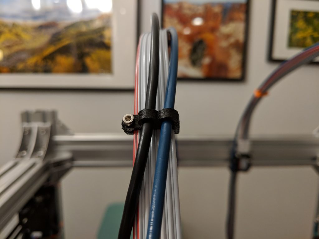
To keep the wires in a nice arc and keep the Bowden attached I made some clips that seem to work great:
Next Up: Lets print something on this bad boy.
Once I get the Left extruder wired to the Duet/Duex main boards, I will be able to start printing. I can’t get the left side (the actual X Axis) working until I am done with the AM8 as I am swapping the Titan Aero from that printer to the new one. I have a handful of important parts to finish printing before I can confidently take the AM8 apart.
I also need to work on the code and setup of the printer in software… it’s not really functional yet, I have a bunch of work to do in RepRap firmware encoding to make it actually function.