This month I was thinking of something fun to do on a trip down to New Mexico to see family (we’ll see if COVID-19 changes those plans though). They happen to live next to White Sands Missile Range, and are all pretty advanced geeks for their age. So.. I figured – I have a 3D printer, I have an interest in space and rockets like they do, and I happen to have a few weeks before I head down there. Why not make my own rockets!? Simple right? Just a tube and some fins…
Going historic
I offered the family the ability to sketch a design and I would model it, print it, and make it fly… well kids are busy and I needed to move forward fast as I had a lot of learning to do on printing rocket parts that are both durable and light. So I went for some historic rockets that White Sands Missile Range (WSMR) has tested and developed as something I could print multiple of to have ready for the kids (all 4 of them). One of the most famous of those rockets are the A4.
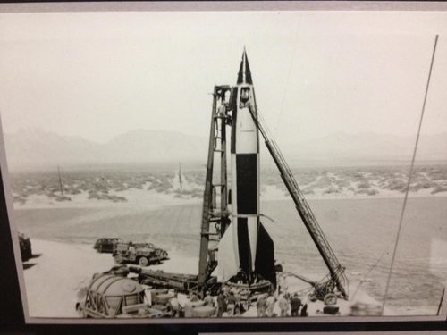
The A4 was the US version of the German V2 rocket that rained fire on London (not good). After the end of the war, the US grabbed a bunch of the scientists, some of the V2s and the gear to make them. They were all moved to Alabama and New Mexico for research and rocket development. The A4 was launched at WSMR in the late 40’s into the 50s and directly lead to the development of the Redstone Rocket that would put Alan Shepard into space in 1961 (good).
Being this rocket was the actual real start to the US space program, it seemed appropriate to model one of them.
Off to Thingiverse
So… I am ok at modeling technical items but I am still really behind the 8 ball on actual high end CAD modeling and such. So instead of trying to design a rocket from scratch as I am pretty time limited I went to Thingiverse to see if anyone had some models I could use. I ran across this model: https://www.thingiverse.com/thing:2496074
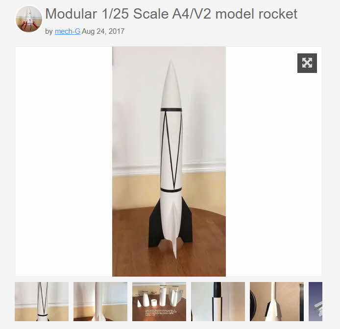
It is a display model with some small additions to let someone make it a flying model. But it lacked the entire motor mount/thrust structure, ejection system, etc… The rocket stands ~22″ – 25″ tall depending on the nose. It is also broken up into parts so its easy to print, and in my case, I can print 2 of each part at the same time. Also this model includes the nose for the WAC Corporal tests performed at WSMR as well.
What are rockets even made of?
Most of my other projects have been relatively tolerant of weight for the sake of stiffness, or needed only one primary property I was worried about. An example would be parts for my 3D printer needed to be rigid at high temp first and foremost, weight was secondary. Same with part for the motorcycle. Other household parts needed to be durable and have some flex, and weight was not a consideration. You get the idea.
I want these rockets durable enough that they can not only take the largest non-licensed motors available, but be able to be launched dozens of times. Balancing re-usability with weight with cost to some extent.
This project needed to have materials that satisfy quite a few requirements as top priorities:
- Light Weight
- Durable (It is going to be subjected to some strong forces on launch and landing)
- High Temp (motor parts, I needed materials that stay strong past 200F)
I happen to have a shelf full of filament. So I went shopping in my office and went with these materials:
- Rocket Body / Ejection System – Matter Hackers NylonG (White and Blue) – its low density glass loaded nylon, is incredibly durable, has good temp resistance, and is fairly easy to print. Layer bonding can be an issue at speed though so dialing in the right settings has been a lot of trial and error that includes me slamming test parts on the edge of the counter to see if they get damaged (rocket science eh?) Its also very smooth and low friction.
- Motor Mount/Thrust Structure/Motor Nut – 3DXtech CarbonX – This is an engineering grade Carbon Fiber loaded Nylon. I had a partial spool of this from last year, it starts to soften at 300F, it is super rigid, and very easy to print (pending the hot end can take it as its ultra abrasive). This filament leaves a very rough/coarse surface. Its marginally heavier than the NylonX or G but has better heat/rigidity properties.
Costs for the materials is not trivial… 750G of CarbonX is around $65, 500G of NylonG is 68. This is 4x+ more expensive than cheap PLA/PETG, but they are amazingly superior materials when handled right. Each Rocket will use about 200G of NylonG, and 100G or so of CarbonX. I am expecting about $30 -$35 in materials in each rocket.
Time to make this model rocket fly
One of the items I was missing in the model I downloaded was the entire motor section. The model had a couple lugs inside of it to accommodate, but they were rudimentary at best. So I was off to FreeCAD to design up an entire motor section of the rocket.
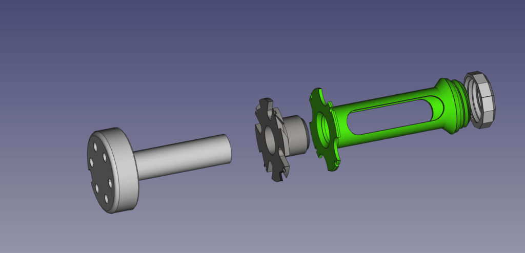
All the motor section parts Left to Right: Ejection Piston/Baffle, Twist on Upper Thrust Structure, Main motor mount with centering rings and lower thrust structure, and threaded motor cap. 
The lower motor mount seated in the anti-twist lugs I put in the fin section.
Lets go Left To Right in the parts above:
- Ejection Baffle/Piston – I was doing some quick reading and it seems since i last launched a rocket back in 1997, stuff has advanced and people are using baffles and pistons to do the ejection instead of just some wadding. This protects the parachute better from hot gas/debris from the ejection charge. I designed this to be light with minimal mass so it doesn’t damage the rocket body when it hits the lug at the top from the ejection force. Its also printed in NylonG to be slippery. It has holes to allow the gas to vent around and through it after the travel up the tube is done.
The rod on the back sits in the thrust structure as a barrel and a bullet to accelerate out of the hole before venting into the rocket body. - Twist on Thrust Structure – Most of the thrust will be connected to the body through the motor nut at the bottom, but I wanted something to back up that and to make the motor section more rigid. So I designed a small twist lock thrust plate that from some testing can take about 10x more weight than the max thrust would ever be on the rocket. It also acts as a barrel to direct the ejection gasses to the piston. Its super strong, and only 10gm.
- Motor Mount – This structure at the top of the motor mount only works to center the mount in the body, and the tube down to the bottom transfers the thrust to the body. The base is the most important part as it is threaded and has a wedge that will lock it and center the base in the body. I have lightened this part considerably over the iterations and its down 1/2 its initial weight (20gm vs 43gm!)
- Motor Nut – this is printed in the same material as motor mount, and secures the mount to the body and the motor in the tube.
Every part of this rocket is just twist locked or fitted with a thread. No glue, tape, or anything is needed for this rocket, making it very easy and quick to work on or replace a part if damaged.
The rest of the parts are largely as is other than the lower fin section which I added some lugs to keep the motor mount from spinning when tightening it down.
I went through a lot of design iterations of these parts focusing on what they need to do, to reduce weight anywhere I can. Print settings have played a major role in that. Just tweaks in the slicer let me see a 15% reduction in weight on the fin section from the initial print. Over all from my first prints/estimates the entire rocket is 100gm lighter down and should be right around 320gm ready to fly.
Printing and Building

All the prototype parts printed – F15-6 motor and Sharpie for scale 
Motor Mount seated in the fin section – this is a older motor mount test, the new one is less beefy. 
Motor mounted and nut installed 
Twist lock thrust plate profile 
Thrust plate installed 
How the Ejection piston fits in the mid body. 
Ejection Piston in the thrust plate


After about 1.5 days of printing non stop I had a full rocket. The first thing I printed was a 7 hour print of the rear fin section. The print settings were wrong and the section is much heavier and messier than I expected… Next one will print in 5 hours and be a full 25% lighter.
The Ejection piston is printed in blue just to use some of the other Blue NylonG I have, and some color is fun.
The full prototype rocket
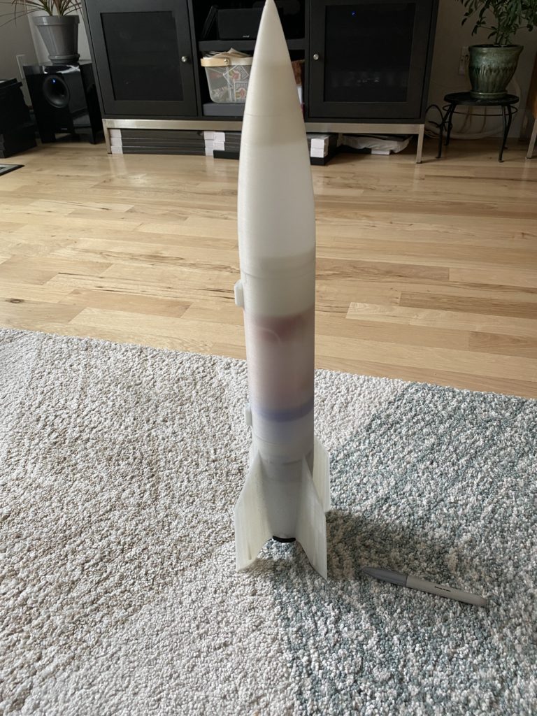
The full rocket completed. Virtually every part on it is already obsolete with changes I made after reviewing the parts, but I believe it should be flight worthy if just heavy. The rocket can take any engine from D – F from Estes. I am going to do a first test flight with a small D12-3 which is a powerful but small engine that may only get the rocket a few hundred feet up which is a fine shake down launch.
I have E and F series motors, and the biggest of them, from some initial math could very well make the lighter versions of the rocket exceed 1500+ft and max well beyond 300knots. For the launches I am designing a holder to throw a GPS data logger in the nose, and potentially a camera mount for the mid body.
Math… god damn math.
Remember in School when teachers told you “Pay attention, when you grow up you’ll need to know this stuff”… well I didnt pay attention in Math classes… I am bad at math… truly awful without a calculator. Most of my life, thats been OK. Well that ends now. Turns out the reason people use Rocket Science as a euphemism for complex things is… well… it uses a shit ton of math.
Good thing is with these low power rockets, you can just kind of wing a lot of things. One thing you cant wing though is “Center of Pressure”. Center of Balance is easy to find with small rockets, just see where it balanced fully loaded and ready to fly. Center of pressure is where all the aerodynamic forces even out. All rocket bodies generate some kind of lift, and some kind of drag… where they converge is center of pressure.
The “Simplified” formula and process to find it:
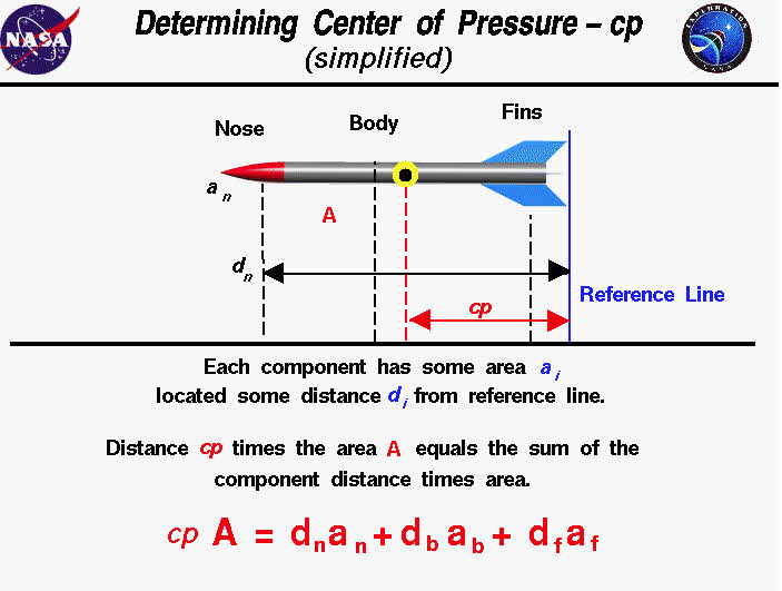
And here it is… fucking calculus.
What happens if CoP is not right? The rocket will tumble at speed and very well may come back toward earth earlier than scheduled. CoP needs to be behind the CoG on the rocket. This generally requires adding weight to the nose of the rocket.
So you can do the math and come up with the exact place the CoP should be for a certain CoG… or… You just tie a string to the COG of the rocket, and spin it over your head. If the rocket keeps aiming forward, you are good to go. If it tumbles, add some weight to the nose and try again.
A nice video explaining this is here:
Next Up – Flight Testing and Mass Production
After I get a flight test under my belt in the coming week and get a few more spools of filament in, I go into full “mass” production. I am going to print 4 rockets (2 of each part at the same time to save time) to take down to New Mexico. I am considering scaling one rocket up 50% as my printer could handle printing the parts 50% bigger than they are… But I need to figure out what motors to use in that case.
I am going to test some paint on my prototype because I want to get it closer to looking like a real A4 tested at WSMR.
This has scratched an itch I did not know I had… and I am already starting to do some initial design work on my own rocket design… but its reminding me I need to 1. get more familiar with my old foe Math, and also maybe learn how to do some more elegant CAD design and not just work with primitives that I normally design with. Its a bold new world!
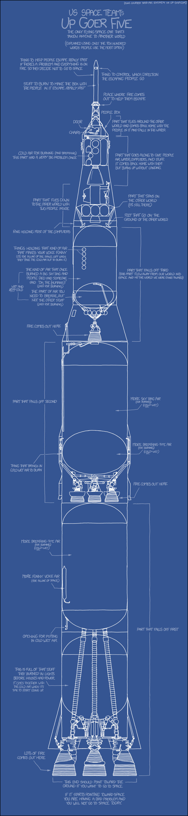
And in closing, one of the best images that describes rockets has to be this: Thanks XKCD for “You will not go to space today” as a common space/rocket term.